Line Grid Rendering
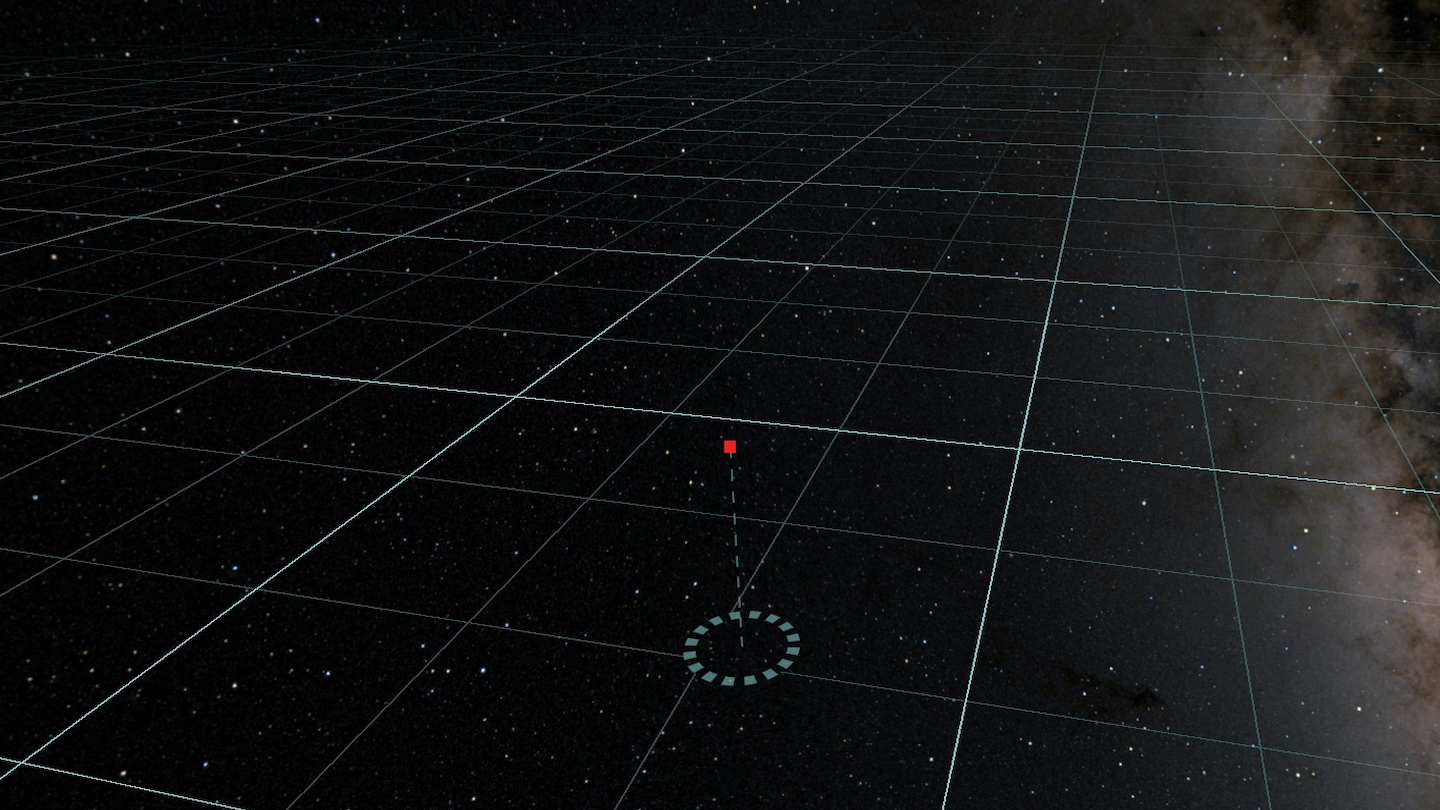
Ephemeris has an "infinite" grid which acts as a reference to help understand the position of things within 3D space. This reference plane should have lines as thin as possible (1 pixel) without suffering from aliasing at any angle or distance.

What Is Aliasing?
In signal processing aliasing occurs when the signal has a higher frequency than the sample rate of a sensor measuring that signal. In graphics this manifests in two ways: temporal aliasing (the image changes faster than 60 fps) and spatial aliasing (there are details in the image smaller than 1 pixel).
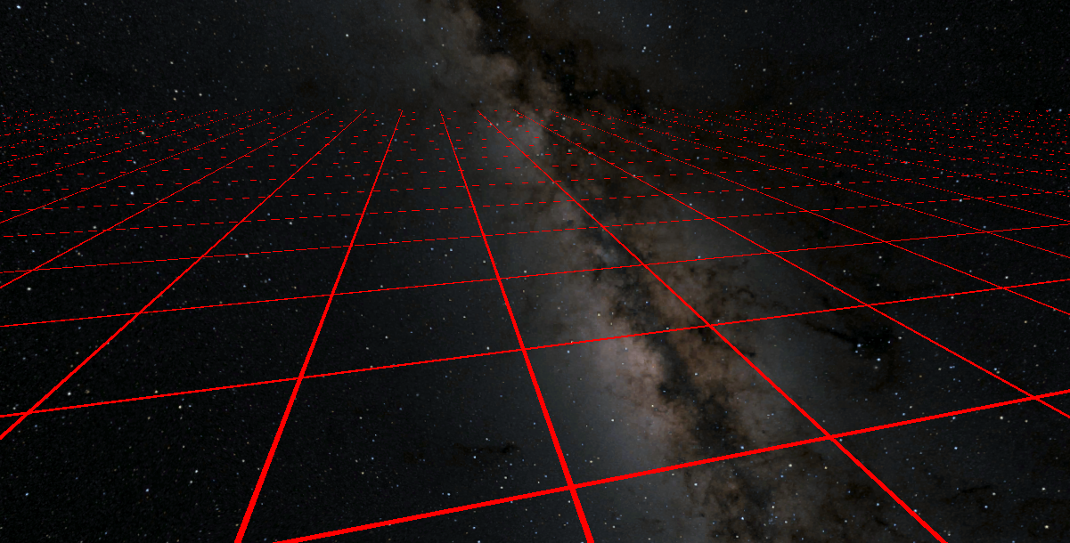
For the line rendering on the grid the lines should be as thin as possible. This presents a problem when choosing the width of the lines, whatever width they are they will be too wide close to the camera and too thin far from the camera! The solution to this is to draw the lines exactly 1 pixel thick no matter the distance from the camera. To give the illusion that the lines disappear into the distance they should fade out to become more transparent in the distance.
Geometry
The basic setup for rendering this grid is that it is a huge quad, stretched out far beyond the camera far-plane. The entire grid plane is just 4 vertices and 2 triangles! A custom shader shades pixels where required to draw the gridlines.
Signed Distance Fields
A classic approach to rendering things using just pixels shaders is to describe the shape of the thing using a signed distance field. Many of the amazing scenes on shadertoy use this technique to great effect. Unity itself uses SDF techniques to render smooth text (a.k.a. TextMeshPro).
A signed distance field is simply a function that tells you the distance to the surface from any point in space. Points which are outside the shape return positive distances, points which are inside the shape return negative distance. You can find a much more in depth explanation of 2D SDF here.
Defining a signed distance field for a 2D 1x1 grid looks like this:
float sdGrid(float2 position)
{
    float2 gridDist = abs(frac(position) - 0.5);
    return min(gridDist.x, gridDist.y);
}
A pixel shader to sample this could look like this:
float g = sdGrid(i.uv);
if (g < WIDTH)
{
    return float4(1, 0, 0, 1);
}
else
{
    return float4(0, 0, 0, 0);
}
However, as discussed above this looks terrible due to aliasing. There is no single WIDTH value that looks good at all distances.

The width could be dynamically selected, such that it is always 1 pixel wide. The best way to do this is to measure the change in the position from one pixel to the next and to constrain the width to that value.
The HLSL ddx and ddy values are somewhat "magical". Calling ddx(value) Tells you the change in that value from this pixel to the next pixel over (in the x and y axes respectively).
Armed with this knowledge a function to select the line width might select a width which is the maximum in either axis:
float width = max(ddx(i.uv.x) + ddy(i.uv.y));
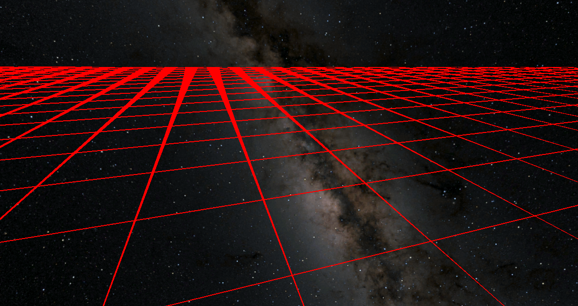
However, this ends up with lines that are too wide in the distance. Scaling the width down by any factor results in aliasing at certain distances.

There are various other tricks for antialiasing 2D signed distance fields, for example you can find more documented here. However I found that none of these techniques worked well for single pixel lines.
Grid Sampling
Since Signed Distance Fields did not seem to be the solution, I came up with a new technique. Given some function to determine a unique ID for a grid cell each pixel can simple calculate all the IDs nearby and if they are not all equal shade itself. The ddx/ddy function can be used to determine how far away to sample (always sampling exactly 1 pixel over).
The function to generate a unique ID for each grid cell can cheat slightly. We don't actually need a unique ID for every grid cell because we're only comparing adjacent cells, so only adjacent cells need to be different. Here's the function for that:
float2 gridIndex(float2 position)
{
    return round(frac(position));
}
The function for sampling this looks quite intimidating at first, but really isn't too bad:
float max2(float2 v)
{
    return max(v.x, v.y);
}

float isLine(float2 position)
{
    // Determine the change in pixel coordate from this pixel to the next one over in x and y axes
    float2 duvx = ddx(position);
    float2 duvy = ddy(position);

    // Where do we want to sample the grid?
    // This is structed as an array to make it easy to add and remove new samples.
    float2 taps[] = {
        float2(1, 1),
        float2(-1, 1),
    };

    // Determine the grid index at "this" pixel
    float2 center = gridIndex(position);

    // Loop over the "taps" array. This is unrolled by the HLSL compiler.
    float accumulator = 0;
    [unroll(taps.Length)] for (uint idx = 0; idx < taps.Length; idx++)
    {
        // Sample the grid at this offset.
        float2 tap = taps[idx];
        float2 gridSample = gridIndex(position + duvx * tap.x + duvy * tap.y);

        // take the absolute difference between samples.
        // Then take the max value of those two.
        // Then take the max of that and the accumulator.
        accumulator = max(accumulator, max2(abs(gridSample - center)));
    }

    // This will be zero if all taps were the same value.
    return accumulator;
}

float4 frag(v2f i) : SV_Target
{
    float line = isLine(i.uv);

    float4 col = float4(1, 0, 0, 1);

    // "line" will be zero if it is the middle of a grid cell, otherwise it will have some other value >= 1.
    col.a *= saturate(line);

    return col;
}
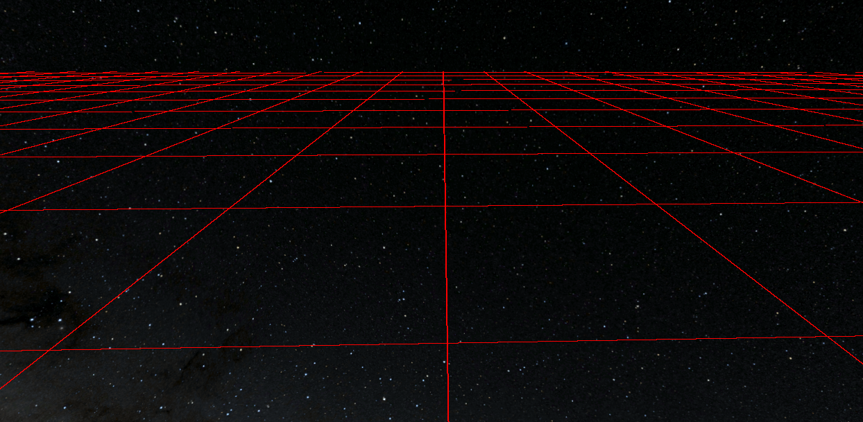
Finally this looks pretty good, except for the hard cut off in the distance (at the camera far plane):

Adding in distance based fading gets us the nice soft fadeout in the distance instead, which also gives the illusion that the lines are getting even thinner in the distance:
